Experimental test on 3D-printing components for Architectural Restoration
Introduction
The field of 3D printing is greatly spreading in recent years in different fields, from manufacturing to healthcare. Indeed, thanks the ability to reproduce complex geometries in a relatively short time frame and its versatility in accommodating a wide range of materials, including eco-sustainable ones, 3D printing has become recently a precious tool in various sectors, as in the spheres of architecture and construction [1,2]. The potential of 3D printing for the realization of customized components with complex designs, while reducing material waste and fabrication time, has led to significant interest in its applications for structural and ornamental elements. Among these, the use of 3D printing for the preservation and rehabilitation of cultural heritage is an innovative area of research [3-7]. Among the various technologies encompassed by Additive Manufacturing (AM), Fused Filament Fabrication (FFF) is one of the most widely used due to its affordability and simplicity. In this process, a thermoplastic filament is heated and extruded through a nozzle to build up the object layer by layer. FFF is particularly suitable for producing complex shapes and small-scale components with minimal material waste.
The combination of 3D printing technologies with digital ones, such as 3D scanning and photogrammetry, has opened new frontiers in the field of architectural restoration. The ability to digitally capture the exact shape and dimensions of historical artifacts, monuments, and buildings allows for the reproduction of missing or damaged parts with a level of accuracy difficult to reach using traditional methods. Several studies have already demonstrated the potential of 3D printing for the physical reintegration of gaps in cultural heritage. For example, literature works show that 3D scanning has been employed to create virtual models of ornamental architectural features, such as the Roman cornice from the Castulo Archaeological Site, and the subsequent use of 3D printing to reproduce the missing parts for reintegration into their original context [8]. Additionally, 3D printing has been applied to reproduce small museum components and repair ancient statues, demonstrating its ability to reproduce historically significant objects with an high level of precision [2,9]. Xu et al. [10] demonstrated that the combination of three-dimensional scanning devices and cement mortar-based 3D printing technology can be effectively used to reproduce ornamental components of historical buildings. In the same context, Papas et al. [11] proposed an approach that involves the combined use of 3D scanning, 3D printing and 3D CAD technologies for the restoration of an ancient terra sigillata plate.
In addition to studies specifically focusing on possible applications of 3D printing, other research works focus the attention on the characteristics of the materials composing the printed elements and their structural performance [4,5]. Indeed, determining the mechanical properties of the materials used for printing is a fundamental challenge, particularly when these materials are employed in restoration projects. The mechanical properties of 3D-printed components are highly influenced by not only the type of material chosen, but also by the parameters chosen for the printing process, such as the layer orientation, printing temperature, filament diameter, print speed and so on
the printed samples under various conditions
Adrover-Monserrat et al. [12] analyzed the effect of the printing direction on the mechanical properties of dog-bone samples printed in polymeric material and on the presence of voids in the cross-section; in particular, considering that all samples were printed with longitudinal layers, three 3D printing orientations have been analyzed, each corresponding to a different layer direction with respect to the application of the load during the tensile tests: layers longitudinal to the direction of force application, layers orthogonal to the force application, and transversal to the force application. The stress stain curves show similar behaviors in terms of initial stiffness, maximum stress and post-peak behavior, nevertheless the last kind of samples show a more brittle behavior, since the detachment between the different layers. Mohd Khairul Nizam et al. [13] have compared elements printed in Acrylonitrile Butadiene Styrene (ABS) with different printing orientations: on-edges, on-flat and up-right; the results showed that the best printing orientation for tensile strength and impact strength is the on-edge, while the best one for hardness is on flat. Kumar et al. [14], analyzed PLA specimens printed by varying different process parameters, such as layer thickness, printing speed and temperature. The samples were realized with a density of
The potential of 3D printing is widely recognized, as evident also from the literature works briefly described. Nevertheless, the idea to employ it in architectural restoration is very recent and still largely unexplored. The novelty of the paper lies in the idea of using a plastic and biodegradable material, such as PLA, for architectural restoration. In this field, the properties of the materials must be carefully assessed to ensure stability and compatibility requirements with existing structures. In this context, it is fundamental to define the material properties in terms of strength and stiffness when designing structural elements. Furthermore, since the mechanical characteristics of the material depend on various printing parameters, it is crucial to be conscious of these factors during the define phase and sample production. In this context, the paper presents the results of tensile tests on dog-bone samples in order to characterize the material properties, followed by tensile and bending tests on small truss-based beam components printed with the same parameters. These components are not part of
an existing restoration intervention but are conceived to explore the feasibility of PLA-based printed structural forms that can be integrated into architectural restoration in future developments. While many previous studies have demonstrated the usefulness of 3D printing in restoration, particularly for reproducing decorative elements or geometrical reconstructions, very few works have focused on assessing the mechanical behavior of structural components made of biodegradable materials such as PLA. In most cases, the printed components are evaluated from an aesthetic or dimensional standpoint, with limited attention to their structural performance under load. Moreover, available mechanical studies often use standardized shapes for material characterization, but do not consider realistic configurations representative of potential architectural components. The aim of this study is to fill this gap by means of the testing of items with a structural justification-a truss-based beam element, in this case-and by reporting experimental results apt for the development of numerical models for the future restoration design. By doing so, the paper moves the state of the art forward by integrating material testing with structural feasibility under a restoration approach, while it promotes the use of sustainable and reversible materials according to principles of conservation. The underlying hypothesis of this study is that PLA, although a biodegradable polymer normally utilized for non-structural applications, can exhibit mechanical behavior enough to deserve consideration for inclusion in structural restoration members. The objective is not the optimization of the printing parameters, but rather to validate a specific configuration through experimental testing, and the assessment of its possible application in future practical use in the conservation of buildings.
This paper deals with a relevant topic within the application of 3D printing technology for architectural and ornamental restoration, contributing to broader research. The practical implications of these studies, include the reconstruction and integration of missing components in historic buildings with linear walls. A notable example is the reproduction of missing battlements in monumental structures, with the aim of placing the printed element in its original position, in order to reconstruct the missing battlement, as proposed by the Authors within the Italian regional projects such as DTC TE1 - Fase II - Progetti RSI (Det. N. G07413 of 16.06.2021, public notice of LAZIO INNOVA) and the research project H-S3D Stampa 3D per Beni Culturali. Applicazioni di Recupero Strutturale e Monitoraggio di Elementi Architettonici e di Decoro.
The combination of 3D printing technologies with digital ones, such as 3D scanning and photogrammetry, has opened new frontiers in the field of architectural restoration. The ability to digitally capture the exact shape and dimensions of historical artifacts, monuments, and buildings allows for the reproduction of missing or damaged parts with a level of accuracy difficult to reach using traditional methods. Several studies have already demonstrated the potential of 3D printing for the physical reintegration of gaps in cultural heritage. For example, literature works show that 3D scanning has been employed to create virtual models of ornamental architectural features, such as the Roman cornice from the Castulo Archaeological Site, and the subsequent use of 3D printing to reproduce the missing parts for reintegration into their original context [8]. Additionally, 3D printing has been applied to reproduce small museum components and repair ancient statues, demonstrating its ability to reproduce historically significant objects with an high level of precision [2,9]. Xu et al. [10] demonstrated that the combination of three-dimensional scanning devices and cement mortar-based 3D printing technology can be effectively used to reproduce ornamental components of historical buildings. In the same context, Papas et al. [11] proposed an approach that involves the combined use of 3D scanning, 3D printing and 3D CAD technologies for the restoration of an ancient terra sigillata plate.
In addition to studies specifically focusing on possible applications of 3D printing, other research works focus the attention on the characteristics of the materials composing the printed elements and their structural performance [4,5]. Indeed, determining the mechanical properties of the materials used for printing is a fundamental challenge, particularly when these materials are employed in restoration projects. The mechanical properties of 3D-printed components are highly influenced by not only the type of material chosen, but also by the parameters chosen for the printing process, such as the layer orientation, printing temperature, filament diameter, print speed and so on
the printed samples under various conditions
Adrover-Monserrat et al. [12] analyzed the effect of the printing direction on the mechanical properties of dog-bone samples printed in polymeric material and on the presence of voids in the cross-section; in particular, considering that all samples were printed with longitudinal layers, three 3D printing orientations have been analyzed, each corresponding to a different layer direction with respect to the application of the load during the tensile tests: layers longitudinal to the direction of force application, layers orthogonal to the force application, and transversal to the force application. The stress stain curves show similar behaviors in terms of initial stiffness, maximum stress and post-peak behavior, nevertheless the last kind of samples show a more brittle behavior, since the detachment between the different layers. Mohd Khairul Nizam et al. [13] have compared elements printed in Acrylonitrile Butadiene Styrene (ABS) with different printing orientations: on-edges, on-flat and up-right; the results showed that the best printing orientation for tensile strength and impact strength is the on-edge, while the best one for hardness is on flat. Kumar et al. [14], analyzed PLA specimens printed by varying different process parameters, such as layer thickness, printing speed and temperature. The samples were realized with a density of
The potential of 3D printing is widely recognized, as evident also from the literature works briefly described. Nevertheless, the idea to employ it in architectural restoration is very recent and still largely unexplored. The novelty of the paper lies in the idea of using a plastic and biodegradable material, such as PLA, for architectural restoration. In this field, the properties of the materials must be carefully assessed to ensure stability and compatibility requirements with existing structures. In this context, it is fundamental to define the material properties in terms of strength and stiffness when designing structural elements. Furthermore, since the mechanical characteristics of the material depend on various printing parameters, it is crucial to be conscious of these factors during the define phase and sample production. In this context, the paper presents the results of tensile tests on dog-bone samples in order to characterize the material properties, followed by tensile and bending tests on small truss-based beam components printed with the same parameters. These components are not part of
an existing restoration intervention but are conceived to explore the feasibility of PLA-based printed structural forms that can be integrated into architectural restoration in future developments. While many previous studies have demonstrated the usefulness of 3D printing in restoration, particularly for reproducing decorative elements or geometrical reconstructions, very few works have focused on assessing the mechanical behavior of structural components made of biodegradable materials such as PLA. In most cases, the printed components are evaluated from an aesthetic or dimensional standpoint, with limited attention to their structural performance under load. Moreover, available mechanical studies often use standardized shapes for material characterization, but do not consider realistic configurations representative of potential architectural components. The aim of this study is to fill this gap by means of the testing of items with a structural justification-a truss-based beam element, in this case-and by reporting experimental results apt for the development of numerical models for the future restoration design. By doing so, the paper moves the state of the art forward by integrating material testing with structural feasibility under a restoration approach, while it promotes the use of sustainable and reversible materials according to principles of conservation. The underlying hypothesis of this study is that PLA, although a biodegradable polymer normally utilized for non-structural applications, can exhibit mechanical behavior enough to deserve consideration for inclusion in structural restoration members. The objective is not the optimization of the printing parameters, but rather to validate a specific configuration through experimental testing, and the assessment of its possible application in future practical use in the conservation of buildings.
This paper deals with a relevant topic within the application of 3D printing technology for architectural and ornamental restoration, contributing to broader research. The practical implications of these studies, include the reconstruction and integration of missing components in historic buildings with linear walls. A notable example is the reproduction of missing battlements in monumental structures, with the aim of placing the printed element in its original position, in order to reconstruct the missing battlement, as proposed by the Authors within the Italian regional projects such as DTC TE1 - Fase II - Progetti RSI (Det. N. G07413 of 16.06.2021, public notice of LAZIO INNOVA) and the research project H-S3D Stampa 3D per Beni Culturali. Applicazioni di Recupero Strutturale e Monitoraggio di Elementi Architettonici e di Decoro.
Motivation
This study aims to explore the potential use of 3D-printed components for the restoration of architectural/structural components. This specifically considers the mechanical characterization of elements strut-printed to simulate structural panels which may have architectural applications. Unlike previous works that often focus on analyzing standard geometric shapes, or aesthetically pleasing copies, the work seems to fill the gap in the literature exploring the mechanics of functionally shaped structures subjected to tension and bending for geared toward restoration design planning analysis. This recovery could be thought in terms both of structural components and decorative ones, considering that in both cases it is fundamental to determine the mechanical properties of the printed element, since even decorative components, such as cornices, should guarantee their own load-bearing capacity. In this context, 3D printing technologies have significant potential, as these allows the creation of even complex geometries with minimal time consumption and material waste. This exploratory study focused on the idea of creating panels with continuous outer edges, while featuring an internal structural pattern that reduces the material usage, resulting in a significantly lower weight compared to solid panels. This approach has been chosen to investigate a simple, easy to be assembled element that is compatible with various applications where it is necessary to fill gaps [7]. The internal pattern analyzed, as will be further discussed in the following sections, is characterized by a truss structure.
The material investigated is PLA, and this choice is motivated by three considerations, strictly related to the necessity of respect the three principle of restoration: recognizability, reversibility and minimum intervention (ICOMOS - accessed in April 23, 2025). First, PLA is a plastic material, easily distinguishable from the masonry that commonly characterize historical buildings, and this feature respect the principle of recognizability. Furthermore, PLA is a biodegradable material, that aligns with environmentally friendly practices, and it is also in line with the second principle of restoration, which is reversibility. Then, PLA is also an affordable material, making it suitable for temporary installations as well; in this framework, its use is compatible with both the principle of reversibility and minimal intervention. Moreover, PLA was selected over other commonly used materials such as ABS and PETG because, unlike these petroleum-based polymers, it is a biodegradable material derived from renewable resources such as corn starch, sugarcane, and cassava. Although PLA biodegrades only under industrial composting conditions, its bio-based origin makes it a more environmentally sustainable option (Filamentive blog - accessed on April 24, 2025; Unionfab blog - accessed on April 24, 2025).
Downstream of this discussion, it is clear that the first step to investigate the use of PLA 3D-printed components, is the mechanical characterization of the material. To this purpose, a part of the paper is dedicated to the results of tensile test
performed on dog-bone (DG) samples. However, it is important to note that the mechanical properties of the specimen do not solely depend on the type of material, but also on a series of parameters that characterize the printing process (orientation of the printing layers, printing temperature, filament diameter, layer dimensions, printing speed, and so on). In this regard, a detailed description of the printing process is provided, and it should be noted that the mechanical properties derived are specific to elements printed with the same process and parameters.
To thoroughly understand the mechanical behavior of 3D-printed PLA components, tensile tests were first conducted on dog-bone samples. These tests aimed to characterize the material in terms of stiffness, strength, and post-peak behavior. Then, structural truss beam samples have been realized and tested to investigate the behavior of potential load-bearing components. The truss beam geometry was selected as it effectively represents a cross-section of a panel with an internal structural pattern. Indeed, the continuous outer flanges of these samples represent the outer walls of a potential 3D-printed panel, while the internal pattern is triangular, mimicking the internal structure of the wall. This design aims to create a lightweight panel that is aesthetically unobtrusive, as the exterior appears to be a continuous surface. These beams have been subjected to tensile tests and three-point bending tests, and the results are discussed also in function of comparisons with DG samples. These two typologies of tests are commonly employed to derive the mechanical properties of samples [5,19-22].
Nevertheless there are numerous existing studies on the mechanical properties of PLA, this paper also presents the results of dog-bone samples tensile test, in order to characterize the material according to the specific printing methods used for the truss beam samples and to verify the compatibility of the results between the different samples in this specific experimental campaign.
The material investigated is PLA, and this choice is motivated by three considerations, strictly related to the necessity of respect the three principle of restoration: recognizability, reversibility and minimum intervention (ICOMOS - accessed in April 23, 2025). First, PLA is a plastic material, easily distinguishable from the masonry that commonly characterize historical buildings, and this feature respect the principle of recognizability. Furthermore, PLA is a biodegradable material, that aligns with environmentally friendly practices, and it is also in line with the second principle of restoration, which is reversibility. Then, PLA is also an affordable material, making it suitable for temporary installations as well; in this framework, its use is compatible with both the principle of reversibility and minimal intervention. Moreover, PLA was selected over other commonly used materials such as ABS and PETG because, unlike these petroleum-based polymers, it is a biodegradable material derived from renewable resources such as corn starch, sugarcane, and cassava. Although PLA biodegrades only under industrial composting conditions, its bio-based origin makes it a more environmentally sustainable option (Filamentive blog - accessed on April 24, 2025; Unionfab blog - accessed on April 24, 2025).
Downstream of this discussion, it is clear that the first step to investigate the use of PLA 3D-printed components, is the mechanical characterization of the material. To this purpose, a part of the paper is dedicated to the results of tensile test
performed on dog-bone (DG) samples. However, it is important to note that the mechanical properties of the specimen do not solely depend on the type of material, but also on a series of parameters that characterize the printing process (orientation of the printing layers, printing temperature, filament diameter, layer dimensions, printing speed, and so on). In this regard, a detailed description of the printing process is provided, and it should be noted that the mechanical properties derived are specific to elements printed with the same process and parameters.
To thoroughly understand the mechanical behavior of 3D-printed PLA components, tensile tests were first conducted on dog-bone samples. These tests aimed to characterize the material in terms of stiffness, strength, and post-peak behavior. Then, structural truss beam samples have been realized and tested to investigate the behavior of potential load-bearing components. The truss beam geometry was selected as it effectively represents a cross-section of a panel with an internal structural pattern. Indeed, the continuous outer flanges of these samples represent the outer walls of a potential 3D-printed panel, while the internal pattern is triangular, mimicking the internal structure of the wall. This design aims to create a lightweight panel that is aesthetically unobtrusive, as the exterior appears to be a continuous surface. These beams have been subjected to tensile tests and three-point bending tests, and the results are discussed also in function of comparisons with DG samples. These two typologies of tests are commonly employed to derive the mechanical properties of samples [5,19-22].
Nevertheless there are numerous existing studies on the mechanical properties of PLA, this paper also presents the results of dog-bone samples tensile test, in order to characterize the material according to the specific printing methods used for the truss beam samples and to verify the compatibility of the results between the different samples in this specific experimental campaign.
MATERIAL AND 3D PRINTING PROCESS
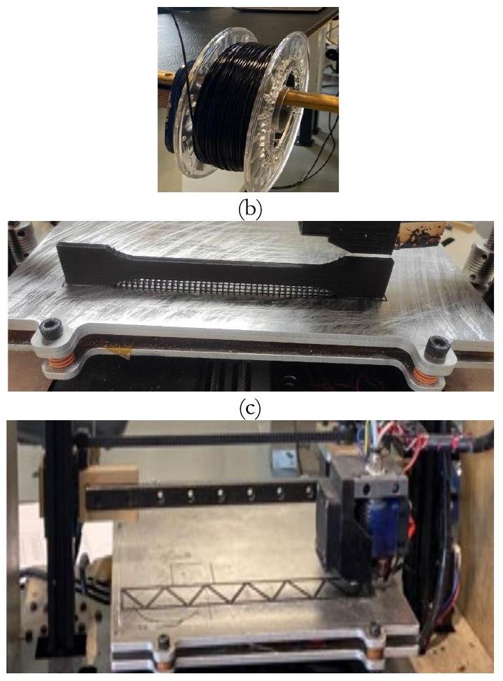
The sample were produced using Additive Manufacturing (AM) technology based on the Fused Filament Fabrication (FFF) process, utilizing PLA as material (Fig. 1b). Specifically, the black RAISE3D Premium PLA filament was employed. The choice of this material is primarily due to its advantages compared to most of the other 3D-printable materials [23].
As previously discussed, the mechanical properties of 3D-printed PLA components are significantly affected by the printing parameters [24]. For the samples under study, the 3D-printing machine used is Araknia two rails (Fig. 1a), and the parameters employed are reported in Tab. 1.
This same printing procedure and parameters were employed for both dog-bone and beam samples. Specifically, for each layer, the perimeter was initially printed with a linear path, followed by the inner area using an alternating inclined path at
As previously discussed, the mechanical properties of 3D-printed PLA components are significantly affected by the printing parameters [24]. For the samples under study, the 3D-printing machine used is Araknia two rails (Fig. 1a), and the parameters employed are reported in Tab. 1.
This same printing procedure and parameters were employed for both dog-bone and beam samples. Specifically, for each layer, the perimeter was initially printed with a linear path, followed by the inner area using an alternating inclined path at
| filament diameter | 1.75 mm |
| minimum/maximum printing temperature | |
| nozzle diameter | 0.4 mm |
| layer thickness | 0.25 mm |
| layer width | 0.5 mm |
| infill percentage | 100% |
| nozzle speed | |
| hot-end temperature |
Table 1: 3D-printing parameters employed.
It should be highlighted that default parameters of the 3D printer used were adopted, with the exception of the layer height that has been increased to 0,25 , in order to increase the production speed of the samples, while respecting the commonly
suggested values to ensure a good printing quality, i.e.
suggested values to ensure a good printing quality, i.e.

(a)
(d)
Figure 1: 3D-printing process: (a) 3D-printing machine; (b) PLA; (c) DG sample with printed support; (d) beam sample during 3Dprinting.

(a)
(b)
Figure 2: 3D-printing process: disposition of subsequent layers during the printing process for (a) DG samples and (b) beam samples.
DESCRIPTION OF SAMPLES AND EXPERIMENTAL TESTS
Dog-bone samples
The Dog-Bone (DG) samples have been manufactured and tested with the aim to explore the behavior of the printed material. For this purpose, tensile tests were conducted on 4 samples, which geometry is described in Fig. 3 and Tab. 2, as suggested by the standards (UNI EN ISO 527-2-2012).

Figure 3: Geometry of dog-bone samples.
| t | r | n. samples | |||||
| DG | |||||||
| 150 | 80 | 20 | 4 | 10 | 20 | 4 |
Table 2: Geometrical dimension and number of DB samples
Beam samples
Beam samples have been manufactured in order to investigate the behavior of 3D-printed structural components. In particular, these samples are characterized by trusses (see Fig. 4) composed of two external flanges connected by an internal structure made of thin walls arranged in a triangular pattern. This pattern is defined by two slope values, denoted as
These beams are referred to as TR_
The geometrical dimensions and the number of samples are summarized in
Tab. 3. Two values of
These beams are referred to as TR_
The geometrical dimensions and the number of samples are summarized in
Tab. 3. Two values of
| t (mm) | w (mm) | n. samples | ||||||
| TR_60 | 200 | 40 | 30 | 4 | 20 | 60 | - | 3 |
| TR_72 | 200 | 40 | 30 | 4 | 20 | 72 | - | 3 |
| BR_60 | 200 | - | 30 | 4 | 20 | 60 | - | 3 |
| BR_72 | 200 | - | 30 | 4 | 20 | 72 | - | 3 |
| BR_60* | 200 | - | 30 | 4 | 20 | 60 | 10 | 3 |
| BR_72* | 200 | - | 30 | 4 | 20 | 72 | 10 | 3 |
Table 3: Geometrical dimensions and number of samples.
It is important to clarify that the infill pattern is the same for both the dog-bone and beam samples, while these differ in terms of overall structure (i.e. geometry). The aim of using beam samples is to analyze the behavior of samples with a specific structural configuration (in this case, trusses), whereas the dog-bone sample is used to characterize the material. To be clearer, the beam specimens have a geometry that was pre-defined and set as input for the 3D printing process. The printing process regulates the infill pattern and infill percentage (

Figure 4: Geometry of beam samples: (a) TR_60 (b) TR_72; (c) BR_60; (d) BR_72; (e) BR_60*; (f) BR_72*.

(a)
Figure 5: Sketch and picture of experimental setups: (a) tension test on DB samples; (b) tension test on beam samples (c) three-point bending test on beam samples.
Experimental setup
The experimental setups are schematically described in Fig.
Southern Lazio by using a universal testing machine Gabaldini (Fig. 4d and f, respectively), while tension test on beam samples have been performed at the laboratory of Pa.L.Mer. in Ferentino (FR), Italy, by using a universal testing machine Instron (Fig. 4e) equipped with tensile load cells and a wedge grip, and a load cylinder with a radius of 10 mm . A speed test of
RESULTS AND DISCUSSION
Dog-bone samples
Tensile tests on DG samples have been carried out in order to characterize the material behavior. The main parameters derived from the tests are the Young's modulus (E) and the tensile strength (
The Young's modulus E was evaluated by considering the force and displacement corresponding to
The Young's modulus E was evaluated by considering the force and displacement corresponding to
where
The values of E and
Actually, the standards (UNI EN ISO 527-2-2012) suggest determining the Young modulus between
Further, the high level of reproducibility of the results is testified by the small value of Coefficient of Variation obtained, reported in Tab. 4. At this stage of the work, potential microstructural defects, such as voids or incomplete bonding between layers, have not been explicitly evaluated, despite their potential influence on the mechanical properties [3]. This choice is based on two main reasons:
Furthermore, the reproducibility of the results suggests that, for the analyzed samples, the microstructural defects are either absent or insignificant in terms of structural performance. Nevertheless, it is important aspect that needs further investigation and will be explored in future studies.
The values of E and
Actually, the standards (UNI EN ISO 527-2-2012) suggest determining the Young modulus between
Further, the high level of reproducibility of the results is testified by the small value of Coefficient of Variation obtained, reported in Tab. 4. At this stage of the work, potential microstructural defects, such as voids or incomplete bonding between layers, have not been explicitly evaluated, despite their potential influence on the mechanical properties [3]. This choice is based on two main reasons:
Furthermore, the reproducibility of the results suggests that, for the analyzed samples, the microstructural defects are either absent or insignificant in terms of structural performance. Nevertheless, it is important aspect that needs further investigation and will be explored in future studies.

Figure 6: Tension tests on dog-bone samples: (a) stress-strain curves and (b) failure modes.
| E (MPa) | ||
| DG_1 | 1341 | 44.3 |
| DG_2 | 1161 | 43.1 |
| DG_3 | 1341 | 44.5 |
| DG_4 | 1229 | 43.1 |
| Average Values | 1270 | 44 |
| Standard Deviation | 76.9 | 0.7 |
| Coefficient of Variation | 6% | 1% |
Table 4: Results deduced from tensile tests in terms of average values of Young's modulus E and strength
Beam samples
The F-
The F-
This observation is further supported by the standard deviation values of the maximum force
| TR_ |
|
| 6890 | |
| 5942 | |
| 6011 | |
| 6738 | |
| 6651 | |
| 6273 | |
| Standard Deviation | 364 |
| Coefficient of Variation | 6% |
Table 5: Maximum forces
|
|
|||||
| 5304 | 5167 | |||||
| 5513 | 5290 | |||||
| 5669 | 5225 | |||||
| 4564 | 4909 | |||||
| 4875 | 5058 | |||||
| 4934 | 5098 | |||||
|
385 | 123 | ||||
| 7% | 2% |
Table 6: Maximum forces Fmax and standard deviation of the values of Fmax of three-point bending tests.
In all the cases, also the three-point bending tests show a brittle behavior, characterized by a sudden failure immediately after reaching the peak load, highlighting an absent post-peak behavior. The brittle behavior is also evident from the picture of the samples after failure (Fig. 10) that show that the specimens collapse approximately at the mid-span of the beam, without evidence of plastic deformations. Moreover, it is evident that the node where the load is applied always fails, except for two BR_60 specimens shown in the Fig. 10a (the first two on the left), which demonstrate that the node where the force is applied does not fail; instead, the adjacent node does. This is due to an off-center load application (caused by the absence of the semi-cylindric housing), which lead to lateral shift of the samples during the experimental test.
Tension Test

Figure 7: Tension test on TR_60/72: Force-Displacement curves.

Figure 8: Picture of samples after tension tests: (a) TR_60; (b) TR_72.
Three-point bending test

Figure 9. Three-point bending test: Force-Displacement curve for (a) BR_60/72 (sample without cylinder) and (b) BR_60*/72* (sample with housing for the load cylinder).
Comparison
In order to have a comparison of the results obtained from the test on the different samples, stress-displacement curves have been evaluated for beam samples subjected to both tension (TR_
About the TR_
About the TR_
The
About the BR_
are the internal forces,
About the BR_
are the internal forces,

Figure 10: Picture of samples after three-point bending tests: (a) BR_60/72 (sample without semi-cylindric housing) and (b) BR_60*/72* (sample with semi-cylindric housing).
The
Considering an average value of maximum normal stress
These findings confirm the consistency and reliability of the experimental results obtained from different testing setups, demonstrating good agreement in terms of stress strength and highlighting the repeatability of the results. Furthermore, the results obtained from the dog-bone samples are useful for characterizing the material in terms of stiffness, strength, and post-peak behavior, providing fundamental information for developing numerical models aimed at predicting the response of structural elements designed with this material. Additionally, the tests performed on the structural samples are crucial for validating any proposed numerical model. In this context, it is important to consider that the information of the material behavior is valid for samples printed with the same parameters described in the previous sections.
For this exploratory study, the focus has been placed on the idea of creating panels with continuous outer edges, while featuring an internal structural pattern that reduces the material usage, resulting in a significantly lower weight compared to solid panels.
The evaluation of the stresses is also useful for better understanding the advantage of using panels with an internal truss structure within the thickness rather than solid panels. In fact, considering a solid panel with a thickness equal to the sum of the thickness of the two flanges of the truss scheme (as if the two flanges are merged to form a solid panel), the same external force applied in a three-point bending test like described in Fig. 11d would result in a much higher stress. For example, considering an applied force F of 3 kN , the corresponding maximum bending stress
These findings confirm the consistency and reliability of the experimental results obtained from different testing setups, demonstrating good agreement in terms of stress strength and highlighting the repeatability of the results. Furthermore, the results obtained from the dog-bone samples are useful for characterizing the material in terms of stiffness, strength, and post-peak behavior, providing fundamental information for developing numerical models aimed at predicting the response of structural elements designed with this material. Additionally, the tests performed on the structural samples are crucial for validating any proposed numerical model. In this context, it is important to consider that the information of the material behavior is valid for samples printed with the same parameters described in the previous sections.
For this exploratory study, the focus has been placed on the idea of creating panels with continuous outer edges, while featuring an internal structural pattern that reduces the material usage, resulting in a significantly lower weight compared to solid panels.
The evaluation of the stresses is also useful for better understanding the advantage of using panels with an internal truss structure within the thickness rather than solid panels. In fact, considering a solid panel with a thickness equal to the sum of the thickness of the two flanges of the truss scheme (as if the two flanges are merged to form a solid panel), the same external force applied in a three-point bending test like described in Fig. 11d would result in a much higher stress. For example, considering an applied force F of 3 kN , the corresponding maximum bending stress
Tension Test

(a)

Figure 11: Stress-displacement curves of beam samples and comparison with maximum stress reached by dog-bone samples: (a) TR_60/72; (b) BR_60/72 (sample without semi-cylindric housing); (c) BR_60*/72* (sample with semi-cylindric housing).
Conclusions
3D printing technology is becoming attractive in the field of restoration of structural/ architectural elements in existing structures. This innovative approach allows for detailed replications of complex shapes and detailed surface features. In such applications, the geometry and size of the 3D-printed components are predetermined a priori, and strictly related to the original element to be restored. However, the disposition of material used to fill the internal volume of the 3D-printed component can be identified as a variable in the realization of lightweight components. In this context, the paper is focused on investigating the potential of 3D-printed PLA components for applications in the field of architectural restoration. The paper provides a preliminary exploratory study in this field, through an experimental campaign. In particular, tensile tests on dog-bone sample have been carried out in order to capture stiffness, strength and post-peak behavior of the material printed with the specific described process and parameters.
A comparison with other experimental studies from the literature would be of interest; however, it is not straightforward due to the wide range and variability of printing parameters involved. Nonetheless, literature tests conducted on specimens printed with
A comparison with other experimental studies from the literature would be of interest; however, it is not straightforward due to the wide range and variability of printing parameters involved. Nonetheless, literature tests conducted on specimens printed with
1300 and 2200 MPa [3,16]. This variability can be attributed to the remaining printing parameters. Despite this, the results obtained in the present study are in line with those reported in the literature.

Figure 12: Structural scheme of the samples in tension tests (a) and three-point bending tests (c), cross-sectional analysis of beam samples subjected to tension tests (b) and three-point bending test (d), cross-sectional analysis of a solid panel subjected to three-point bending test (e).
On the other hand, small structural truss beams have been realized with the same process and parameters of DG samples, and have been subjected to tensile and bending tests, in order to explore their structural behavior. In particular, the truss beam samples have been thought as a potential section of a panel characterized by a continuous external surface, and an internal triangular truss patterns aimed to reduce the weight with respect a solid panel. This preliminary investigation is crucial in understanding the mechanical properties of the structural components, fundamental for a successive phase of design of structural elements. The obtained values of tensile strength have been derived from the tests mentioned before, investigating two typologies of tests (tensile and three-point bending tests) and two kinds of samples (dog-bone and truss) considering a total of 22 samples. Although the number of tested samples is limited and does not comply with the minimum requirements of standards such as UNE-EN ISO 527 and 178 (which recommend at least five specimens per series), the results show a good level of reproducibility, as confirmed by the coefficients of variation below
The obtained results are based on quasi-static tests developed in short-term, where the load is gradually increased until failure. As such, they do not provide information on the long-term behavior of the material, which is influenced by timedependent phenomena such as creep, fatigue and viscosity, characteristic of polymeric materials [25], which require dedicated studies. Another crucial consideration is the biodegradability of PLA, which may lead to changes in its mechanical properties over time. In this regard, existing literature provides results from accelerated aging tests [6], which indicate that while aging causes significant deformations, it does not lead to substantial variations in mechanical properties. At present, the findings do not take into account the log-term behavior of the material, anyway this study can be effectively applied for the preliminary design of installations, which can also be temporary, since can be easily replaced thanks to the cost-
effectiveness of the material. Indeed, as an immediate development, the obtained results can be employed in order to create numerical models able to predicts the behavior of PLA components, by using the results of tensile tests on dog-bone sample to model the materials, and the results of tensile and bending tests of beams to validate the numerical model.
This paper deals with a relevant topic within the application of 3D printing technology for architectural and ornamental restoration, contributing to a broader research. The practical implications of these studies, include the reconstruction and integration of missing components in historic buildings with linear walls. A notable example is the reproduction of missing battlements in monumental structures, as proposed by the Authors within the Italian regional projects such as DTC TE1 Fase II - Progetti RSI (Det. N. G07413 of 16.06.2021, public notice of LAZIO INNOVA) and the research project H-S3DStampa 3D per Beni Culturali. Applicazioni di Recupero Strutturale e Monitoraggio di Elementi Architettonici e di Decoro.
Moreover, 3D printing enables the realization of complex designs, allowing for the efficient and simple reproduction also of ornamental elements due to its ability to produce complex geometries without significant difficulties. The experimental results obtained in this study suggest that 3D-printed PLA components can be effectively considered for real-world restoration applications, particularly for the reproduction of lightweight architectural elements and partial structural integrations. For large-scale projects, such as the restoration of missing sections in walls, battlements, parapets, or ornamental facades, the proposed 3D printing approach allows the creation of customized components that can be integrated into existing structures while ensuring reversibility and compatibility. Moreover, thanks to the reduced weight achieved through internal truss patterns, these components could be employed without significantly increasing the loads acting on historical masonry structures, thereby preserving their original stability. Future developments based on this work will aim to design and test larger panels and modular elements suitable for pilot applications in real restoration projects.
The obtained results are based on quasi-static tests developed in short-term, where the load is gradually increased until failure. As such, they do not provide information on the long-term behavior of the material, which is influenced by timedependent phenomena such as creep, fatigue and viscosity, characteristic of polymeric materials [25], which require dedicated studies. Another crucial consideration is the biodegradability of PLA, which may lead to changes in its mechanical properties over time. In this regard, existing literature provides results from accelerated aging tests [6], which indicate that while aging causes significant deformations, it does not lead to substantial variations in mechanical properties. At present, the findings do not take into account the log-term behavior of the material, anyway this study can be effectively applied for the preliminary design of installations, which can also be temporary, since can be easily replaced thanks to the cost-
effectiveness of the material. Indeed, as an immediate development, the obtained results can be employed in order to create numerical models able to predicts the behavior of PLA components, by using the results of tensile tests on dog-bone sample to model the materials, and the results of tensile and bending tests of beams to validate the numerical model.
This paper deals with a relevant topic within the application of 3D printing technology for architectural and ornamental restoration, contributing to a broader research. The practical implications of these studies, include the reconstruction and integration of missing components in historic buildings with linear walls. A notable example is the reproduction of missing battlements in monumental structures, as proposed by the Authors within the Italian regional projects such as DTC TE1 Fase II - Progetti RSI (Det. N. G07413 of 16.06.2021, public notice of LAZIO INNOVA) and the research project H-S3DStampa 3D per Beni Culturali. Applicazioni di Recupero Strutturale e Monitoraggio di Elementi Architettonici e di Decoro.
Moreover, 3D printing enables the realization of complex designs, allowing for the efficient and simple reproduction also of ornamental elements due to its ability to produce complex geometries without significant difficulties. The experimental results obtained in this study suggest that 3D-printed PLA components can be effectively considered for real-world restoration applications, particularly for the reproduction of lightweight architectural elements and partial structural integrations. For large-scale projects, such as the restoration of missing sections in walls, battlements, parapets, or ornamental facades, the proposed 3D printing approach allows the creation of customized components that can be integrated into existing structures while ensuring reversibility and compatibility. Moreover, thanks to the reduced weight achieved through internal truss patterns, these components could be employed without significantly increasing the loads acting on historical masonry structures, thereby preserving their original stability. Future developments based on this work will aim to design and test larger panels and modular elements suitable for pilot applications in real restoration projects.
References
[1] Pajonk, A., Prieto, A., Blum, U., Knaack, U. (2022). Multi-material additive manufacturing in architecture and construction: A review, J. Build. Eng., 45, pp. 103603, DOI: 10.1016/J.JOBE.2021.103603.
[2] Kantaros, A., Ganetsos, T., Petrescu, F.I.T. (2023). Three-Dimensional Printing and 3D Scanning: Emerging Technologies Exhibiting High Potential in the Field of Cultural Heritage, Appl. Sci., 13(8), 4777. DOI: 10.3390/APP13084777.
[3] Monaldo, E., Ricci, M., Marfia, S. (2023). Mechanical properties of 3D printed polylactic acid elements: Experimental and numerical insights, Mech. Mater., 177, 104551, DOI: 10.1016/j.mechmat.2022.104551.
[4] Tanikella, N.G., Wittbrodt, B., Pearce, J.M. (2017). Tensile strength of commercial polymer materials for fused filament fabrication 3D printing, Addit. Manuf., 15, pp. 40-47, DOI: 10.1016/j.addma.2017.03.005.
[5] Song, Y., Li, Y., Song, W., Yee, K., Lee, K.-Y., Tagarielli, V.L. (2017). Measurements of the mechanical response of unidirectional 3D-printed PLA, Mater. Des., 123, pp. 154-164, DOI: 10.1016/j.matdes.2017.03.051.
[6] Tomei, V., Grande, E., Caponero, M.A., Imbimbo, M. (2024). 3D-printing for the rehabilitation and health monitoring of structures with FBG: Experimental tests, Constr. Build. Mater., 416, 135067, DOI: 10.1016/j.conbuildmat.2024.135067.
[7] Tomei, V., Grande, E., Imbimbo, M. (2024). Optimization of the internal structure of 3D-printed components for architectural restoration, Fract. Struct. Integr., 18(70), pp. 227-241, DOI: 10.3221/IGF-ESIS.70.13.
[8] Higueras, M., Calero, A.I., Collado-Montero, F.J. (2021). Digital 3D modeling using photogrammetry and 3D printing applied to the restoration of a Hispano-Roman architectural ornament, Digit. Appl. Archaeol. Cult. Herit., 20, pp. e00179, DOI: 10.1016/j.daach.2021.e00179.
[9] Almerbati, N., Dustin, H. (2016).Heritage conservation in the new digital era: The benefits of 3D printing architecture screens in sustaining architecture and identity. The fourth international conference for Heritage conservation, sustainable heritage: global vision, local experience.
[10] Xu, J., Ding, L., Love, P.E.D. (2017). Digital reproduction of historical building ornamental components: From 3D scanning to 3D printing, Autom. Constr., 76, pp. 85-96, DOI: 10.1016/j.autcon.2017.01.010.
[11] Papas, N., Tsongas, K., Karolidis, D., Tzetzis, D. (2023). The integration of 3D technologies and finite element analysis (FEA) for the restoration of an ancient terra sigillata plate, Digit. Appl. Archaeol. Cult. Herit., 28, pp. e00260, DOI: 10.1016/j.daach.2023.e00260.
[12] Adrover-Monserrat, B., García-Vilana, S., Sánchez-Molina, D., Llumà, J., Jerez-Mesa, R., Martinez-Gonzalez, E., Travieso-Rodriguez, J.A. (2023). Impact of printing orientation on inter and intra-layer bonds in 3D printed thermoplastic elastomers: A study using acoustic emission and tensile tests, Polymer (Guildf)., 283, pp. 126241, DOI: 10.1016/J.POLYMER.2023.126241.
[13] Mohd Khairul Nizam, M.A.N. bin., Ismail, K.I. bin., Yap, T.C. (2022). The Effect of Printing Orientation on the Mechanical Properties of FDM 3D Printed Parts, Lect. Notes Mech. Eng., , pp. 75-85, DOI: 10.1007/978-981-19-2890-1_8.
[14] Kumar, M.S., Farooq, M.U., Ross, N.S., Yang, C.H., Kavimani, V., Adediran, A.A. (2023). Achieving effective interlayer bonding of PLA parts during the material extrusion process with enhanced mechanical properties, Sci. Reports 2023 131, 13(1), pp. 1-21, DOI: 10.1038/s41598-023-33510-7.
[15] Fontana, L., Minetola, P., Iuliano, L., Rifuggiato, S., Khandpur, M.S., Stiuso, V. (2022). An investigation of the influence of 3d printing parameters on the tensile strength of PLA material, Mater. Today Proc., 57, pp. 657-663, DOI: 10.1016/J.MATPR.2022.02.078.
[16] Hanon, M.M., Dobos, J., Zsidai, L. (2021). The influence of 3D printing process parameters on the mechanical performance of PLA polymer and its correlation with hardness, Procedia Manuf., 54, pp. 244-249, DOI: 10.1016/J.PROMFG.2021.07.038.
[17] Hamoud, M., Elshalakany, A.B., Gamil, M., Mohamed, H. (2024). Investigating the influence of 3D printing parameters on the mechanical characteristics of FDM fabricated (PLA/Cu) composite material, Int. J. Adv. Manuf. Technol., 134(78), pp. 3769-3785, DOI: 10.1007/S00170-024-14313-0/TABLES/6.
[18] Sultana, J., Rahman, M.M., Wang, Y., Ahmed, A., Xiaohu, C. (2024). Influences of 3D printing parameters on the mechanical properties of wood PLA filament: an experimental analysis by Taguchi method, Prog. Addit. Manuf., 9(4), pp. 1239-1251, DOI: 10.1007/S40964-023-00516-6/FIGURES/7.
[19] Zhao, Y., Chen, Y., Zhou, Y. (2019). Novel mechanical models of tensile strength and elastic property of FDM AM PLA materials: Experimental and theoretical analyses, Mater. Des., 181, pp. 108089, DOI: 10.1016/J.MATDES.2019.108089.
[20] Yao, T., Ye, J., Deng, Z., Zhang, K., Ma, Y., Ouyang, H. (2020). Tensile failure strength and separation angle of FDM 3D printing PLA material: Experimental and theoretical analyses, Compos. Part B Eng., 188, pp. 107894, DOI: 10.1016/j.compositesb.2020.107894.
[21] Rajpurohit, S.R., Dave, H.K. (2018). Flexural strength of fused filament fabricated (FFF) PLA parts on an open-source 3D printer, Adv. Manuf., 6(4), pp. 430-441, DOI: 10.1007/S40436-018-0237-6.
[22] Pastor-Artigues, M.M., Roure-Fernández, F., Ayneto-Gubert, X., Bonada-Bo, J., Pérez-Guindal, E., Buj-Corral, I. (2019). Elastic Asymmetry of PLA Material in FDM-Printed Parts: Considerations Concerning Experimental Characterisation for Use in Numerical Simulations, Mater., 13(1), pp. 15, DOI: 10.3390/MA13010015.
[23] Yao, T., Deng, Z., Zhang, K., Li, S. (2019). A method to predict the ultimate tensile strength of 3D printing polylactic acid (PLA) materials with different printing orientations, Compos. Part B Eng., 163, pp. 393-402, DOI:10.1016/j.compositesb.2019.01.025.
[24] Wittbrodt, B., Pearce, J.M. (2015). The effects of PLA color on material properties of 3-D printed components, Addit. Manuf., 8, pp. 110-116, DOI: 10.1016/j.addma.2015.09.006.
[25]Jimenez-Martinez, M., Varela-Soriano, J., Carreón, J.J.R., Torres-Cedillo, S.G. (2023). Mechanical fatigue of PLA in additive manufacturing, Eng. Fail. Anal., 149, pp. 107273, DOI: 10.1016/J.ENGFAILANAL.2023.107273.
[2] Kantaros, A., Ganetsos, T., Petrescu, F.I.T. (2023). Three-Dimensional Printing and 3D Scanning: Emerging Technologies Exhibiting High Potential in the Field of Cultural Heritage, Appl. Sci., 13(8), 4777. DOI: 10.3390/APP13084777.
[3] Monaldo, E., Ricci, M., Marfia, S. (2023). Mechanical properties of 3D printed polylactic acid elements: Experimental and numerical insights, Mech. Mater., 177, 104551, DOI: 10.1016/j.mechmat.2022.104551.
[4] Tanikella, N.G., Wittbrodt, B., Pearce, J.M. (2017). Tensile strength of commercial polymer materials for fused filament fabrication 3D printing, Addit. Manuf., 15, pp. 40-47, DOI: 10.1016/j.addma.2017.03.005.
[5] Song, Y., Li, Y., Song, W., Yee, K., Lee, K.-Y., Tagarielli, V.L. (2017). Measurements of the mechanical response of unidirectional 3D-printed PLA, Mater. Des., 123, pp. 154-164, DOI: 10.1016/j.matdes.2017.03.051.
[6] Tomei, V., Grande, E., Caponero, M.A., Imbimbo, M. (2024). 3D-printing for the rehabilitation and health monitoring of structures with FBG: Experimental tests, Constr. Build. Mater., 416, 135067, DOI: 10.1016/j.conbuildmat.2024.135067.
[7] Tomei, V., Grande, E., Imbimbo, M. (2024). Optimization of the internal structure of 3D-printed components for architectural restoration, Fract. Struct. Integr., 18(70), pp. 227-241, DOI: 10.3221/IGF-ESIS.70.13.
[8] Higueras, M., Calero, A.I., Collado-Montero, F.J. (2021). Digital 3D modeling using photogrammetry and 3D printing applied to the restoration of a Hispano-Roman architectural ornament, Digit. Appl. Archaeol. Cult. Herit., 20, pp. e00179, DOI: 10.1016/j.daach.2021.e00179.
[9] Almerbati, N., Dustin, H. (2016).Heritage conservation in the new digital era: The benefits of 3D printing architecture screens in sustaining architecture and identity. The fourth international conference for Heritage conservation, sustainable heritage: global vision, local experience.
[10] Xu, J., Ding, L., Love, P.E.D. (2017). Digital reproduction of historical building ornamental components: From 3D scanning to 3D printing, Autom. Constr., 76, pp. 85-96, DOI: 10.1016/j.autcon.2017.01.010.
[11] Papas, N., Tsongas, K., Karolidis, D., Tzetzis, D. (2023). The integration of 3D technologies and finite element analysis (FEA) for the restoration of an ancient terra sigillata plate, Digit. Appl. Archaeol. Cult. Herit., 28, pp. e00260, DOI: 10.1016/j.daach.2023.e00260.
[12] Adrover-Monserrat, B., García-Vilana, S., Sánchez-Molina, D., Llumà, J., Jerez-Mesa, R., Martinez-Gonzalez, E., Travieso-Rodriguez, J.A. (2023). Impact of printing orientation on inter and intra-layer bonds in 3D printed thermoplastic elastomers: A study using acoustic emission and tensile tests, Polymer (Guildf)., 283, pp. 126241, DOI: 10.1016/J.POLYMER.2023.126241.
[13] Mohd Khairul Nizam, M.A.N. bin., Ismail, K.I. bin., Yap, T.C. (2022). The Effect of Printing Orientation on the Mechanical Properties of FDM 3D Printed Parts, Lect. Notes Mech. Eng., , pp. 75-85, DOI: 10.1007/978-981-19-2890-1_8.
[14] Kumar, M.S., Farooq, M.U., Ross, N.S., Yang, C.H., Kavimani, V., Adediran, A.A. (2023). Achieving effective interlayer bonding of PLA parts during the material extrusion process with enhanced mechanical properties, Sci. Reports 2023 131, 13(1), pp. 1-21, DOI: 10.1038/s41598-023-33510-7.
[15] Fontana, L., Minetola, P., Iuliano, L., Rifuggiato, S., Khandpur, M.S., Stiuso, V. (2022). An investigation of the influence of 3d printing parameters on the tensile strength of PLA material, Mater. Today Proc., 57, pp. 657-663, DOI: 10.1016/J.MATPR.2022.02.078.
[16] Hanon, M.M., Dobos, J., Zsidai, L. (2021). The influence of 3D printing process parameters on the mechanical performance of PLA polymer and its correlation with hardness, Procedia Manuf., 54, pp. 244-249, DOI: 10.1016/J.PROMFG.2021.07.038.
[17] Hamoud, M., Elshalakany, A.B., Gamil, M., Mohamed, H. (2024). Investigating the influence of 3D printing parameters on the mechanical characteristics of FDM fabricated (PLA/Cu) composite material, Int. J. Adv. Manuf. Technol., 134(78), pp. 3769-3785, DOI: 10.1007/S00170-024-14313-0/TABLES/6.
[18] Sultana, J., Rahman, M.M., Wang, Y., Ahmed, A., Xiaohu, C. (2024). Influences of 3D printing parameters on the mechanical properties of wood PLA filament: an experimental analysis by Taguchi method, Prog. Addit. Manuf., 9(4), pp. 1239-1251, DOI: 10.1007/S40964-023-00516-6/FIGURES/7.
[19] Zhao, Y., Chen, Y., Zhou, Y. (2019). Novel mechanical models of tensile strength and elastic property of FDM AM PLA materials: Experimental and theoretical analyses, Mater. Des., 181, pp. 108089, DOI: 10.1016/J.MATDES.2019.108089.
[20] Yao, T., Ye, J., Deng, Z., Zhang, K., Ma, Y., Ouyang, H. (2020). Tensile failure strength and separation angle of FDM 3D printing PLA material: Experimental and theoretical analyses, Compos. Part B Eng., 188, pp. 107894, DOI: 10.1016/j.compositesb.2020.107894.
[21] Rajpurohit, S.R., Dave, H.K. (2018). Flexural strength of fused filament fabricated (FFF) PLA parts on an open-source 3D printer, Adv. Manuf., 6(4), pp. 430-441, DOI: 10.1007/S40436-018-0237-6.
[22] Pastor-Artigues, M.M., Roure-Fernández, F., Ayneto-Gubert, X., Bonada-Bo, J., Pérez-Guindal, E., Buj-Corral, I. (2019). Elastic Asymmetry of PLA Material in FDM-Printed Parts: Considerations Concerning Experimental Characterisation for Use in Numerical Simulations, Mater., 13(1), pp. 15, DOI: 10.3390/MA13010015.
[23] Yao, T., Deng, Z., Zhang, K., Li, S. (2019). A method to predict the ultimate tensile strength of 3D printing polylactic acid (PLA) materials with different printing orientations, Compos. Part B Eng., 163, pp. 393-402, DOI:10.1016/j.compositesb.2019.01.025.
[24] Wittbrodt, B., Pearce, J.M. (2015). The effects of PLA color on material properties of 3-D printed components, Addit. Manuf., 8, pp. 110-116, DOI: 10.1016/j.addma.2015.09.006.
[25]Jimenez-Martinez, M., Varela-Soriano, J., Carreón, J.J.R., Torres-Cedillo, S.G. (2023). Mechanical fatigue of PLA in additive manufacturing, Eng. Fail. Anal., 149, pp. 107273, DOI: 10.1016/J.ENGFAILANAL.2023.107273.